Build log · in progress
SCARA × PLC
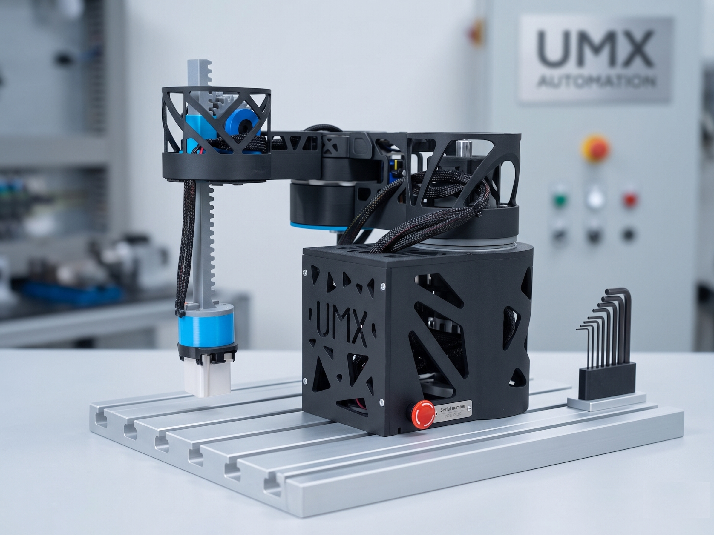
A 3-axis SCARA arm driven by an ESP32 and orchestrated by a real industrial PLC over Modbus. The point: prove that hobby-grade firmware and industrial control can share the same factory floor — without one pretending to be the other. Built in public as my Mechatronics diploma project.
Status
in progress
Started
Q1 2026
Target
Diploma defense · Q3 2026
Stack
L1 → L4
01 — Bill of design decisions
What it is, in one table.
- Topology
- 3-axis SCARA + linear Z
- Controller (motion)
- ESP32-S3
- Controller (logic)
- Mitsubishi FX-series PLC · Structured Text
- Bus
- Modbus RTU over RS-485
- Drives
- NEMA17 + closed-loop drivers
- Frame
- 3D-printed + aluminium extrusions
- Software
- C++ firmware · Structured Text (PLC) · Python tooling
02 — Why
Why an ESP32 next to a PLC.
Industrial logic doesn't have to mean industrial prices, and hobby firmware doesn't have to be unsafe — but treating them as interchangeable is how projects fail. A PLC is excellent at supervisory control: deterministic scan time, certified safety, ladder logic any maintenance technician can read at 3am. An ESP32 is excellent at the things a PLC is bad at: cheap I/O, fast loops, modern toolchains, wireless OTA.
The bridge between them is a contract — a Modbus register map. Once that contract is honest, both sides can evolve independently. That's the same lesson I learned the hard way running production infrastructure: services don't fail because the code is wrong, they fail because the contract between them is fuzzy.
03 — Log
Updates, in order.
-
2026 · Q1
Kickoff + scope
Split: PLC owns supervisory logic, safety interlocks, and the operator interface. ESP32 owns motion planning, step generation, and homing. Modbus RTU as the bridge.
-
2026 · Q1–Q2
Mechanical CAD freeze
Locking the arm geometry in SolidWorks — link lengths, bearing seats, end-effector mount. Once frozen, kinematics math gets hard-coded into the firmware.
-
2026 · Q2
PCB v0.1
ESP32-S3 carrier with isolated RS-485, 4× stepper driver headers, an emergency-stop input wired through an opto-isolator, and a 24V → 5V buck.
-
2026 · Q2
Modbus register map
Define what the PLC and ESP32 exchange — target pose, speed, current state, fault flags, e-stop ack. Get this right and both sides can evolve independently.